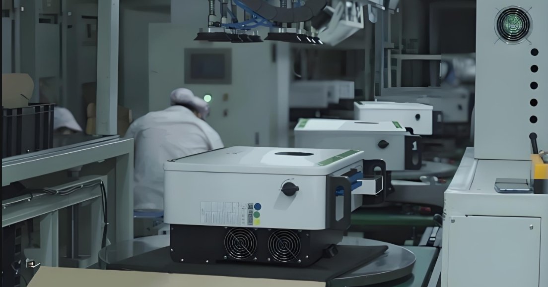
Inverters are essential for converting DC power into AC, but how do they work? Let’s break it down step by step.
Inverters transform DC power into AC through several processes like switching, pulse generation, modulation, and control systems. Let’s explore these in more detail.
Understanding the internal mechanisms of an inverter helps you choose the right one for your needs. Keep reading to discover how each part works.
Switching Mechanism
The switching mechanism is at the core of an inverter’s function. It’s responsible for converting DC power into AC by rapidly switching the input current on and off at high speeds.
Switching inverters involves rapidly turning the power on and off to create the alternating current.
Transistor-Based Switching
In modern inverters, transistors like MOSFETs and IGBTs1 are used for switching. These semiconductor devices allow for rapid switching of current, which is crucial for creating the alternating nature of AC power.
Pulse Width Modulation (PWM)
Pulse Width Modulation (PWM)2 controls the timing and duration of each switch to generate a smoother, more controlled AC waveform. By adjusting the pulse width, the inverter can approximate the smooth sine wave that is needed.
Efficiency Considerations
The efficiency of the switching mechanism is crucial. High-speed transistors and optimized switching techniques minimize losses, ensuring that the inverter operates efficiently, even at high power levels.
| Component | Function | Benefit |
|---|---|---|
| Transistor | Rapid switching of DC | Allows for high-speed conversion |
| PWM | Controls switching intervals | Ensures smooth AC output |
Pulse Generation
Once the switching occurs, the next step is pulse generation. Inverters create high-frequency pulses that will be shaped into a sine wave for the final AC output.
Pulse generation is the initial step in shaping DC into AC by creating high-frequency pulses.
High-Frequency Oscillators
High-frequency oscillators3 generate the raw pulses that form the foundation of the AC output. These oscillators typically create square waves, which are later transformed into more refined waveforms.
Conversion to Sine Wave
The raw pulses generated need to be shaped into a smooth sine wave4 to ensure the output is suitable for household appliances and sensitive devices. This shaping is a key part of the pulse generation process.
Impact on Power Quality
The quality of the pulse generation directly affects the inverter's overall power output. Inverters with better pulse generation can provide cleaner, more reliable energy for sensitive electronics.
| Step | Description | Impact |
|---|---|---|
| Pulse Generation | High-frequency oscillators create raw pulses | Forms the basis of AC output |
| Conversion | Pulses are shaped into a sine wave | Determines power quality |
Modulation Techniques
Modulation techniques are employed to refine the output waveform. These techniques allow the inverter to create a higher quality AC signal, closely matching the ideal sine wave.
Modulation techniques refine the output waveform, ensuring that the inverter’s AC power meets the necessary quality and voltage specifications.
Sinusoidal Pulse Width Modulation (SPWM)
Sinusoidal Pulse Width Modulation (SPWM)5 is the most common modulation method. It adjusts the pulse width to create an AC waveform that closely approximates a sine wave, ensuring minimal harmonic distortion.
Multi-Level Modulation
Multi-level modulation6 is used in more advanced inverters. It generates a waveform with multiple voltage levels, which reduces harmonic distortion and improves the overall quality of the AC output.
Frequency Control
Frequency control ensures that the inverter’s output matches the required grid or load frequency. By adjusting the output frequency, inverters can provide reliable power for different types of equipment.
| Modulation Technique | Description | Benefit |
|---|---|---|
| SPWM | Adjusts pulse width for a sine wave | Minimizes harmonic distortion |
| Multi-Level Modulation | Uses multiple voltage levels | Reduces distortion further |
| Frequency Control | Adjusts output frequency | Ensures compatibility with devices |
Control Systems
Control systems are the "brains" of the inverter, coordinating all the functions to ensure that the inverter works efficiently and safely. These systems manage the switching, pulse generation, modulation, and other internal processes.
Control systems monitor and optimize the inverter’s performance, ensuring smooth and efficient operation.
Microcontrollers and Digital Signal Processors (DSP)
Microcontrollers and DSP7 are used to monitor and manage the various functions. These systems analyze inputs like voltage, current, and frequency, and adjust the operation of the inverter accordingly.
Protection Features
Protection features8 include safety mechanisms such as overcurrent protection, thermal management, and fault detection. These features prevent the inverter from damaging itself or connected devices by shutting down when abnormal conditions are detected.
Communication and Monitoring
Many modern inverters come with communication capabilities that allow for remote monitoring. Control systems allow users to track performance, troubleshoot issues, and even update firmware remotely for better efficiency.
| Feature | Function | Benefit |
|---|---|---|
| Microcontrollers | Monitor and control inverter operation | Ensures smooth performance |
| Protection Features | Includes safety mechanisms like overcurrent protection | Prevents damage to the inverter and devices |
| Communication | Allows remote monitoring and updates | Enhances convenience and control |
Conclusion
Inverters use switching, pulse generation, modulation techniques, and control systems to efficiently convert DC to AC. Each part of the process is essential for ensuring that the inverter produces high-quality and reliable power.
Footnotes:
-
This link explains the role of MOSFETs and IGBTs in inverter switching, focusing on their speed and efficiency. ↩
-
This link provides an overview of PWM and its importance in generating smooth AC waveforms in inverters. ↩
-
This link explains the role of high-frequency oscillators in generating raw pulses for AC conversion. ↩
-
This link discusses the process of shaping inverter pulses into smooth sine waves for clean power output. ↩
-
This link explains how SPWM creates high-quality AC waveforms with minimal distortion. ↩
-
This link explores how multi-level modulation reduces harmonic distortion and enhances power quality. ↩
-
This link explains the role of microcontrollers and DSPs in managing inverter functions effectively. ↩
-
This link outlines the protection features like overcurrent and thermal management in inverters. ↩


